Mechanical design and prototyping
Rendering of swingarm internal assembly
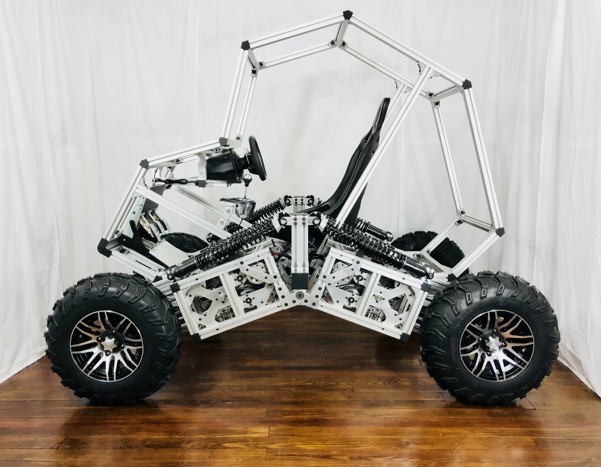
Completed mechanical assembly
Swingarm mount
Swingarm internal assembly
Underside of completed prototype
Steering knuckle/hub/axle assembly
Height adjustment winch
Drive chain and steering cable housings
Steering cable winch with planetary gear reduction
Rendering of full as-built mechanical assembly, containing approx. 8,000 parts
Electrical design and prototyping
Hand-soldered 2-layer prototype motor driver PCB
PCB layout with MOSFET bridge, gate driver, current sensing/digitization, and encoder connection
MOSFET full bridge and gate drive circuit
3D rendering of prototype motor driver PCB
Bottom view showing via stitching on high-current paths
Two motor driver prototype PCBs being tested
Xilinx block diagram of Zynq FPGA/processor system configuration. Several small VHDL modules were used to test communication with various components of the motor driver board before being integrated in to a single module to control each pair of motors.
Simple iOS app created to send commands to Zynq processor and receive feedback during testing
Two custom PCBs made to provide isolated connection between 5V driver board signals and the 3.3V FPGA i/o on the development board's PMOD connectors
MOSFET gate voltage ringing during turn on/off
Testing of the incremental rotary optical encoders that are used to measure the speed of each motor
Cable routing from motors, encoders, and height/steering angle sensors
Automotive throttle position sensors mounted on custom brackets to measure the steering angle of each wheel
Fabrication
Steering cable winch spools were manually machined from 7075 aluminum. Two parts were machined together until the final parting step to allow sufficient material to be held in the lathe chuck.
6061 aluminum turned, faced, drilled, and bored
M10-1.5 tapped through holes
Custom shaft support for attaching swingarms to frame
Custom sensor shafts machined from hex rod stock
4mm keyways milled into steel shaft
Spot drilling for countersunk M5 flat head screw clearance holes
TiAlN-coated carbide was used to drill through these hardened steel gears.
Hub o.d. turned down from 30mm to 29mm to fit a standard sprocket
CAD sketch of part designed for waterjet cutting
Automated part nesting for waterjet cutting
Manually adding tabs, waterjet paths, and cutting speeds
Waterjet cutting 1/8" 6061
Parts still attached to sheet via tabs
1/4" 7075 waterjet parts after countersinking on drill press with self-centering single flute countersink
Parts after deburring and finishing with maroon Scotch-Brite pad
Oilite bushing pressed into plate after reaming waterjet hole to H7 tolerance
Steering cable housing being bent from 1/2" aluminum tubing
Bushing pressed into gear hub
Aluminum profile extrusion assembly
13mm holes milled into extrusions
Part nesting for laser cutting
Laser cutting 1/8" Delrin
Laser cutting 1/32" Delrin
Innovative design
The innovative differential power sharing mechanism allows the combined output of each group of two motors to be divided as needed between wheel traction and either steering or ride height adjustment.
Steering motor group
Height adjustment motor group
The symmetric quad swingarm design was developed to allow maximum ride height adjustment, to allow independent control of each wheel's traction, steering, and height, and to allow a single swingarm design to be used for all four wheels.
Rendering showing all four swingarms fully lowered
With all four swingarms fully raised, the frame-to-ground clearance is approximately 30in.
Iterative prototyping
Rendering of first frame design
Wooden prototype of second frame design
Rendering of third frame design
MISUMI configurable components were used whenever possible to minimize the number of custom machined parts required.
Laser cut 1/4" MDF was used to confirm the fit of parts prior to cutting them from 1/4" or 1/2" aluminum plate.
Laser cut 1/8" Delrin was used to check parts before waterjet cutting.
First swingarm design, made with MISUMI configurable components
Second swingarm design, with temporary laser cut MDF and plywood parts
Third swingarm design
First knuckle mount design, made with MISUMI configurable components
Second knuckle mount design
Third knuckle mount design
First swingarm design testing
Simple breadboard circuit created to control a pair of off-the-shelf motor controllers via an Arduino before developing the FPGA motor controller and custom driver PCBs
Prototyping MOSFET bridge with through hole version of gate driver chip